Industrial Helical Gearbox

Helical Gearbox
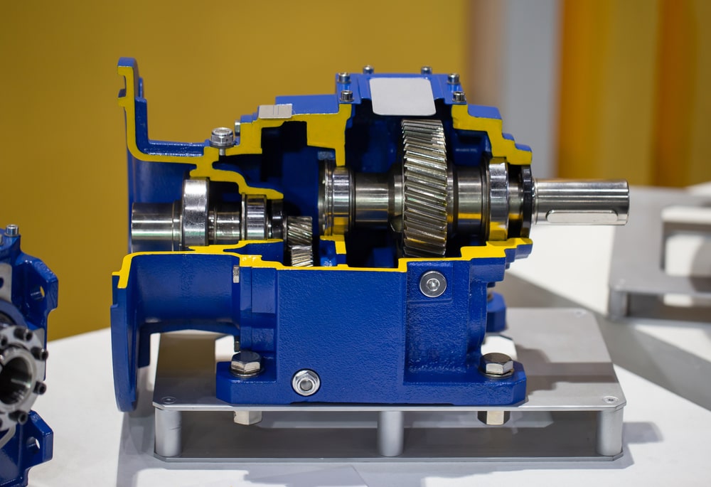
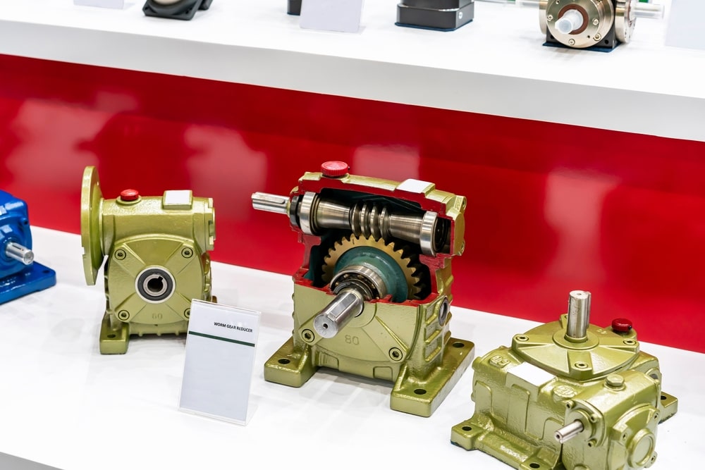
Industrial Gearboxes square measure utilized in several small-scale and large-scale industries and notice a broad vary of applications. There square measure some skilled leading industrial gear case constructors round the world. They focus on the assembly of various industrial gearboxes like spiral gear case, Worm gear case, Planetary gear case, and engaged Motors. during this post, we'll discuss the spiral gear case and its working rule, efficiency, and applications in additional detail.
What Is Helical Gearbox ?
Helical Gearbox area unit one among the foremost wide used gearboxes and that they area unit more practical than the other gearbox. Their configuration facilitates several performances.
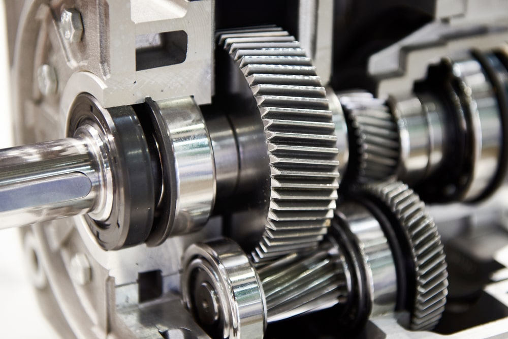
Helical gears square measure one form of cylindrical gears wherever the teeth square measure falcate into a helix form. Compared to spur gears (straight teeth), properly designed voluted gears will have a bigger total contact magnitude relation which may improve vibration and noise.
Definition Of Helical Gears
Helical gears area unit power transmission instruments primarily used to scale back speed and increase force between turning shafts. essentially, they'll be divided into 2 forms, people who transmit energy between parallel components and people that transfer power between non-parallel elements, usually introduced as cross-axis gears. whereas a whorled gear in section read has the identical involute tooth form like cogwheel, it's cut at associate degree angle to the circulation of the gear blank. This angle is introduced because the angle. whorled gears area unit explained below, together with a discussion of their performance and usual applications.

Helical gears contain special teeth that area unit placed at a selected angle to the shaft. This ends up in over one tooth being involved throughout the perform, creating the gear capable of tolerating a lot of load. This configuration additionally permits whorled gears to perform quieter and drum sander than spur gears owing to the load sharing between teeth.
The standard model and production of the whorled gear case give many engineering and performance blessings, containing a high degree of interchangeableness of elements and sub-assemblies. This offers for economical construction whereas keeping the most effective normal of part integrity.
Helical Gearbox Working Principle
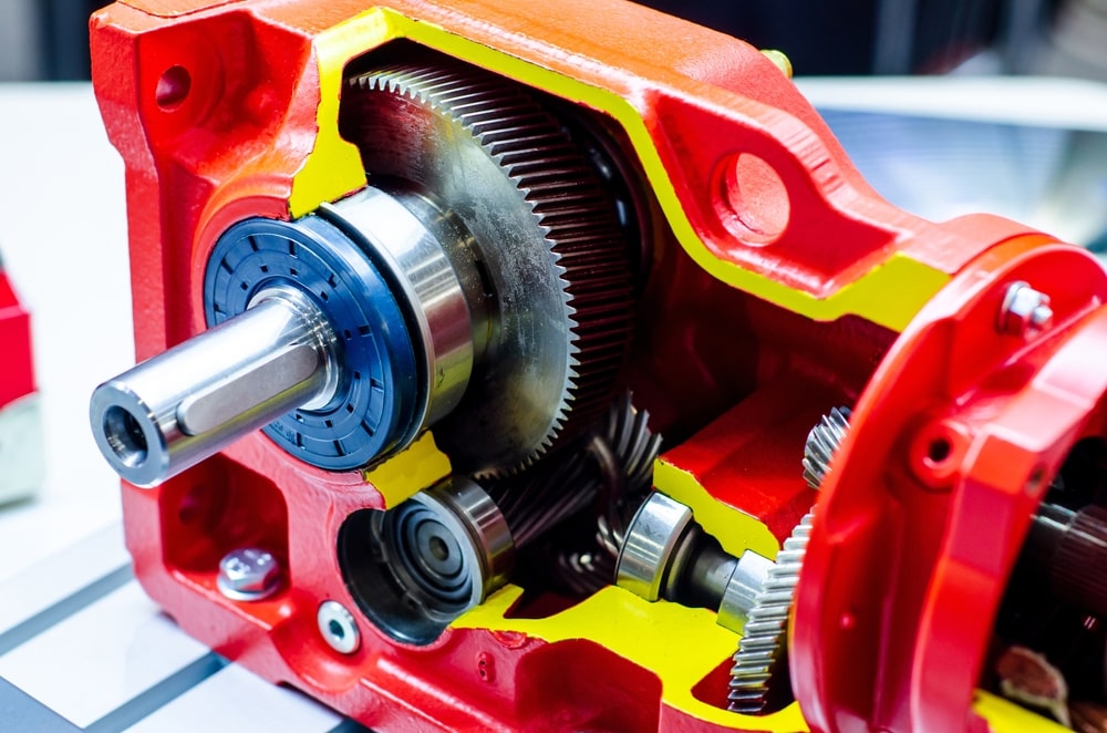
There are a number of helical gears in a helical gearbox. Helical gears are a particular type of cylindrical gear with a slanted tooth trace. They outperform spur gears in terms of silence, vibration, contact level, and capacity to transfer heavier loads. Even if a set of helical gears has the same helix angle, the helix hand is on the other side.
The spur gear hobbing tool and hobbing machine can be used to produce helical gears when the reference part of the gear is in the standard form and the hobbing instrument is tilted. Teeth are twisted during fabrication, which has the drawback of more difficult construction.
As was previously noted, helical gears can be divided into two types based on where their reference section is located: in the turning plane transverse module and the standard plane normal module. As long as the reference component has the same module and number of teeth as the spur gears, the centre gap is the same if it is in the turning plane. This makes switching spur gears easy.
But for this application, they require specialised hobbing cutters and grinding stones, which raises the cost of construction. If the reference component is in the normal plane, it is still possible to use grinding stones and spur gear hobbing tools. However, swapping becomes extremely difficult because the centre gap of helical gears and the identical module and number of teeth in spur gears no longer match. The centre gap is also frequently not an integer.
Helical gears provide axial thrust loads even though spur gears do not because of the twist in the tooth trace. Therefore, using thrust bearings to take on this stress is appropriate. The thrust force can be eliminated by building double-helical gears by merging left- and right-hand helical gears.
In automotive transmission applications, spur gears are often replaced by helical gears. In contrast to spur kinds, helical gears and helical gearboxes have the potential to operate smoothly. Based on the gear's face, the teeth on a helical gear are cut at a unique angle. As a result, during operation, when two of the teeth start to engage, the contact progressively starts at one area of the tooth and is maintained until the gear engages fully. The most common gears used for transferring are of the helical form, which may also generate a lot of thrust.
Fundamentals of Helical Gearbox Operation
A spur gear set with a 0° helix angle is technically a helical gearbox. Helix angles typically range between 15° and 30° for helical kinds. The 20° involute spur, which is the typical gear tooth type, is identified. 14-1/2° involute spur gears were common at the time, but they are no longer the norm. The pressure angle of the tooth refers to these latter degree requirements. The two teeth follow a line of touching as they enter and exit the main mesh.

Only the involute gears of individual teeth will maintain the same pressure angle during the meshing. The primary teeth form is brilliant because it exhibits theoretically stable velocity ratios even when the centre gaps are not totally fixed. Sometimes referred to as the fundamental rule of gearing, this necessity for a fixed velocity ratio.
The best way to grasp a helical gearbox is to picture a lot of identical spur gears made out of paper and connected such that each new section moves a little bit forward of the one before it. Such a setup would need the mating gear to stagger its sections in the opposite direction in order for it to function. Since they are mounted on parallel shafts, mated helical gears are unquestionably left- and right-handed.
Thrust forces result from being heavy handed, which are not produced by spur gears mating. Helical gear models need to have roller or ball bearings that can handle axial loading to handle this thrust loading.
Advantages of Helical Gearbox
When looking at the paper design once more, it is easy to observe how each layer of the spur gears mates with its counterpart progressively before the next portion makes contact, in contrast to spur gears, where touching occurs simultaneously along the full tooth face. More teeth are in contact at any given time due to the wider spacing between each tooth. In comparison to spur kinds, the helical gearbox transmits loads more smoothly. As a result, there is an increase in speed potential, quieter operation, and load capacity. The following is a list of some benefits of helical gearboxes over other types:
| Helical gears and gearboxes are typically strong and ideal for high-load applications. |
|---|
| It may be used to transmit force and motion between shafts with a right or parallel angle. |
| The helical gearbox performs at lower efficiency than spur kinds because of the thrust forces and increased sliding friction between components. |
| For smoother operation, the angled teeth engage more gradually than spur gear teeth. |
How Effective Helical Gearboxes Are
The basic efficiency of the helical gearbox set is high, ranging from 90% to 99.5%, and it has parallel shaft gears and a typical all-rolling touch mesh.
Modules with radial and normal edges
The normal perpendicular to teeth module arrangement is used by some types of involute helical gearboxes, while others use the radial (perpendicular to the shaft) module layout, which has different tooth form reference sections.
Professional builders offer two lineups of radial module arrangements series and regular module system kinds in addition to typical helical gears, and we will explain the key distinctions between the two below.
The typical module set of the helical gearbox has the advantage of being able to use the same spur gear tooth-cutting tools, like grinding and hob stones. To put it another way, they can be built more affordably than the recently developed radial module type of helical gears that was later explained. To change spur gears with the same module and number of teeth, helical gears cannot be performed without varying the centre gap, which is a drawback of the standard module system. Otherwise, the pitch circle diameter depends on the helix angle, compared to the identical module and number of teeth in spur gears.
Maintaining the centre gap to the easily controllable integer numbers is hard as well. The opposite of the typical module structure is the radial type's principal advantage and merit. The first benefit to be noted is that since the actual pitch value is lower than the typical pitch even with the helix angle, it is possible to replace them with spur kinds that have the same module and number of teeth while maintaining the same centre gap. Concerning a disadvantage, since the actual radial pitch differs with each helix angle, it becomes necessary to acquire hobs and grinding wheels for each helix angle, practically increasing production costs.
Why Use Helical Gearboxes?
A set of cylindrical gears with teeth that aren't perpendicular to the turning axis are used in helical gearboxes. The teeth are a section of a helix that appears to be transforming power between axes at right angles or parallel angles. A helical gearbox differs fundamentally from other types in that its teeth form a helix and have the ability to run more silently. Another benefit of using these gearboxes is that they have a greater capacity for power transmission between two parallel shafts than spur gears with an identical width and similar module. Additionally, since the force will be shared among numerous teeth, there will be less wear and strain. There are several adaptations of a helical gearbox depending on their needs for applications in various sectors.
Applications of Helical Gearbox
Helical gearboxes are recommended by the majority of reputed industrial gearbox manufacturers to run under heavy power efficiency and, of course, when we need silent performance, such as in automotive systems. Some of them consist of:
| Elevators, conveyors, compressors, blowers, oil industries, textile and food industries, as well as cutters |
|---|
| Applications for steel, rolling mills, power, and ports |
| Industries such as printing, fertiliser, and earth moving |
A excellent example of the quietness of helical kinds is the sound that a manual transmission system makes when it is being operated in reverse. The reason for that distinct whine is that reverse instruments are reversed using spur forms so they can be "changed"—all other instruments are constant mesh. For the forward velocities, helical gears are used, which are exceptionally silent. For the low range, when speeds are modest and the noise is not bothersome, some 4-wheel drive transfer systems use spur types.

Both helical- and spur-gear designs of industrial gearboxes are available. The specifics of a particular case are at the centre of the discussion on which to use. Helical kinds make sense when noise is an issue, especially if the gear train will operate at medium to high velocities. Spur gearing may be a better approach where there are limitations on space or weight is a factor since it requires fewer power thrust-carrying bearings. Spur gears often cost cheaper to make than helical gearboxes, albeit the difference is only marginally significant. The model includes costs for the more durable shaft bearings and supports needed for helical gears.
This debate takes parallel shafts into account. For cross-axis shafts, the choice now is between helical, worm, and bevel gearing rather than spur and helical gears. Helical kinds offer a less expensive way to transmit power across crossed shafts, but they are less capable of carrying large loads than their parallel counterparts. One typical use for crossed-axis helical types is the gear pair used to drive the oil pump/distributor shaft in car engines.
Despite costing more, bevel gears have a substantially higher capacity than helical gears. Worm gears offer significant reduction levels, but due to the significant sliding friction they produce, they require heat management and lubrication.
Spur types can occasionally be used as direct replacements for herringbone gears, although their more expensive production makes them more efficient. In extremely large transmission applications, such as shipboard basic reduction gears, herringbone gears are frequently employed.
The majority of gears are made of cast iron, AGMA grade 20, but there are higher grades available for stronger gears at a higher cost. To achieve a better balance to component wear, steel is consistently used as a pinion material meshing with a cast iron gear. Since heat treatment can cause gears to deform, it is often only employed on gears constructed of alloy steels. The tooth profiles can be improved through grinding after heating. Additionally, gears are made using bronze. Diverse plastics are also employed in the production of gears, sometimes as the gear that meshes with a cast iron or steel pinion.
There are numerous other uses in addition to the ones mentioned above. Helical gearboxes and helical gears have a wide range of applications. Watch the area carefully to learn more.
The industry's most efficient machinery, Helical Gearboxes operate at 98% efficiency, second only to Planetary kinds.
For smoother operation, the angled teeth engage more gradually than spur shape teeth. Both helical gears and helical gearboxes are typically robust and ideal for high-load applications. It may be able to move and transmit electricity between parallel and right-angle setups.
They also have uses in low-power systems including extruders, crushers, cranes, coolers, mixers, and conveyors in addition to the aforementioned ones.
